Showing posts with label Engineering. Show all posts

Thursday, September 13, 2012

Transformers are normally protected against short circuits and overheating. Transformer protections justifiable in different installations will vary widely depending upon the size of the equipment, importance as a unit part of the Distribution system, and its voltage rating. Small distribution Transformers maybe protected by fuses while larger ones in feeder circuit or at injection substations may be equipped with various types of protective equipment varying from long-time overcurrent to high speed differential protection, standby earth fault relay, bucholz gas relay, etc.

Relay Coordination

This exercise aids selectivity of operation in an interconnected system. The discrimination using overcurrent protection is achieved in these ways:
  • Time Graded System : Based on the time of operation of relays
  • Current Graded System: Adopted where the fault current varies appreciably with location.
  • Time Current Graded System: This type of grading is achieved using inverse time overcurrent relay and the most widely used is the IDMT relay.

Lightening Protection

Lightening strikes can cause damage to poles, failure to Transformer, puncturing insulators or underground cables and blowing of fuses. Damage may also occur to meters or appliances in the premises of the Transformer.
In order to protect the transformer and other elements of the network, the schemes usually employed include:
  • Installation of Lightening Arresters
  • Grounding of all the circuits
  • Aerial earthing of substation
Analog Signal Conditioning provides the operations necessary to transform a sensor output into a form necessary to interface with other elements of the process control loop.
Signal Conditioning can be classified into various types:
  • Linearization
  • Conversions
  • Filtering and Impedance Matching
  • Concept of Loading

Linearization 

The purpose of linearization is to provide an output that varies linearly with some variable even if the sensor output does not.

Conversions

Often, Signal Conditioning is used to convert one type of electrical variation into another. Two types of conversion are:

  • Signal Transmission
  • Digital Interface

Signal Transmission 

This gives rise to the need for converting resistance and voltage levels to an appropriate current level at the transmitting end and for converting the current back to voltage at the receiving end.

Digital Interface

The use of computers in process control necessitates the conversion of analog data into digital format by IC devices called A/D converters(Analog-Digital Converters).

Filtering and Impedance Matching

Often, spurious signals of considerable strengths are present in industrial envirouments. In many of such cases, it is necessary to use high-pass, low pass, or notch filters to eliminate unwanted signals from the loop. This might be accomplished by :
  • Passive Filters(using Resistors, Capacitors and Inductors)
  • Active Filters(using gain and feedback)


Tuesday, September 11, 2012

By transposition of conductors, we mean the exchanging of the position of the power conductors at regular intervals along the line so that each conductor occupies the original position of every other conductor over an equal distance. If the spacing is unequal, even though the system operates under balanced condition, voltage drops of different magnitude will be there in the 3 conductors due to unequal inductance in the 3-phase. Also due to unsymmetrical spacing, the magnetic field external to the conductors is not zero, thereby causing induced voltages in adjacent electrical circuits particularly telephone lines,  that may result in interference. To reduce this effect, the conductors are transposed as shown below:
Transposition of Conductors


It is enough to transpose either the power lines or the communication lines under balanced operating conditions, the magnetic field linking an adjacent telephone line is shifted 120 degrees in the time phase with each relation of the conductor positions in the transposition cycle. Over the length of one complete transposition cycle of power lines, the net voltage induced in the telephone lines is zero as it is the sum of the 3 induced voltages which are displaced by 120 degrees in time phase under balanced conditions of course.

Monday, September 10, 2012

The basic function of an Excitation system is to provide direct current to the synchronous machine field winding. It also performs CONTROL and PROTECTIVE FUNCTIONS essential to the satisfactory performance of the power system by controlling the field voltage and thereby the field current.

Modeling of Excitation Systems

•Mathematical models of Excitation systems are essential for the assessment of desired performance requirements ,for the design and coordination of supplementary control and protective circuits, and for system stability studies related to the planning and operation of power systems.
•The detail of the model required depends on the purpose of the study.
•Referring to the figure below the control and protective features that impact on the transient and small signal stability studies are the voltage regulators, power system stabilizer, excitation control stabilization.
•The limiter and protective circuits identified in the figure normally need to be considered only for the mid term,long,and voltage stability studies.
•Some excitation systems are provided with fast acting terminal voltage limiters in conjunction with power system stabilizers.
•These have to be modeled in transient stability simulations.
The Modeling(Mathematical Model) is divided into three parts:
  • Model of Amplifier
  • Model of Exciter
  • Model of Generator


Monday, May 07, 2012

Field Instrumentation

Field Instrumentation refers to the sensors and actuators that are directly interfaced to the plant or equipment. They generate the analog and digital signals that will be monitored by the Remote Station. Signals are also conditioned to make sure they are compatible with the inputs/outputs of the RTU or PLC at the Remote Station.
Field Instrumentation refers to the devices that are connected to the equipment or machines being controlled and monitored by the SCADA system. These are sensors for monitoring certain parameters; and actuators for controlling certain modules of the system.These instruments convert physical parameters (i.e., fluid flow, velocity, fluid level, etc.) to electrical signals (i.e., voltage or current) readable by the Remote Station equipment. Outputs can either be in analog (continuous range) or in digital (discrete values). Some of the industry standard analog outputs of these sensors are 0 to 5 volts, 0 to 10 volts, 4 to 20 mA and 0 to 20 mA. The voltage outputs are used when the sensors are installed near the controllers (RTU or PLC). The current outputs are used when the sensors are located far from the controllers.
Digital outputs are used to differentiate the discrete status of the equipment. Usually, <1> is used to mean EQUIPMENT ON and <0> for EQUIPMENT OFF status. This may also mean <1> for FULL or <0> for EMPTY.
Actuators are used to turn on or turn off certain equipment. Likewise, digital and analog inputs are used for control. For example, digital inputs can be used to turn on and off modules on equipment. While analog inputs are used to control the speed of a motor or the position of a motorized valve.

The Remote Station

The Remote Station is installed at the remote plant or equipment being monitored and controlled by the central host computer. This can be a Remote Terminal Unit (RTU) or a Programmable Logic Controller (PLC). Field instrumentation connected to the plant or equipment being monitored and controlled are interfaced to the Remote Station to allow process manipulation at a remote site. It is also used to gather data from the equipment and transfer them to the central SCADA system. The Remote Station may either be an RTU (Remote Terminal Unit) or a PLC (Programmable Logic Controller). It may also be a single board or modular unit. 
The RTU (Remote Terminal Unit) is a ruggedized computer with very good radio interfacing. It is used in situations where communications are more difficult. One disadvantage of the RTU is its poor programmability. However, modern RTUs are now offering good programmability comparable to PLCs. The PLC (Programmable Logic Controller) is a small industrial computer usually found in factories. Its main use is to replace the relay logic of a plant or process. Today, the PLC is being used in SCADA systems to due its very good programmability. Earlier PLC’s have no serial communication ports for interfacing to radio for transferring of data. Nowadays, PLC's have extensive communication features and a wide support for popular radio units being used for SCADA system. In the near future we are seeing the merging of the RTUs and the PLC’s. Micrologic is offering an inexpensive RTU for SCADA system wherein the PLC may be an overkill solution. It is a microcontroller-based RTU and can be interfaced to radio modems for transmitting of data to the CMS.
Remote Terminal Unit (RTU)
Programmable Logic Controller
Programmable Logic Controller (PLC)

The Communications Network

The Communications Network is the medium for transferring information from one location to another. This can be via telephone line, radio or cable. The Communication Network refers to the communication equipment needed to transfer data to and from different sites. The medium used can either be cable, telephone or radio. The use of cable is usually implemented in a factory. This is not practical for systems covering large geographical areas because of the high cost of the cables, conduits and the extensive labor in installing them. The use of telephone lines (i.e., leased or dial-up) is a cheaper solution for systems with large coverage. The leased line is used for systems requiring on-line connection with the remote stations. This is expensive since one telephone line will be needed per site. Besides leased lines are more expensive than ordinary telephone line. Dial-up lines can be used on systems requiring updates at regular intervals (e.g., hourly updates). Here ordinary telephone lines can be used. The host can dial a particular number of a remote site to get the readings and send commands. Remote sites are usually not accessible by telephone lines. The use of radio offers an economical solution. Radio modems are used to connect the remote sites to the host. An on-line operation can also be implemented on the radio system. For locations wherein a direct radio link cannot be established, a radio repeater is used to link these sites.

Central Monitoring Station

The Central Monitoring Station (CMS) refers to the location of the master or host computer. Several workstation may be configured on the CMS, if necessary. It uses a Man Machine Interface (MMI) program to monitor various types data needed for the operation. The following is a sample configuration of a SCADA system for water distribution.
The Central Monitoring Station (CMS) is the master unit of the SCADA system. It is in charge of collecting information gathered by the remote stations and of generating necessary action for any event detected. The CMS can have a single computer configuration or it can be networked to workstations to allow sharing of information from the SCADA system.
A Man-Machine Interface (MMI) program will be running on the CMS computer. A mimic diagram of the whole plant or process can be displayed onscreen for easier identification with the real system. Each I/O point of the remote units can be displayed with corresponding graphical representation and the present I/O reading. The flow reading can be displayed on a graphical representation of a flowmeter. A reservoir can be displayed with the corresponding fluid contents depending on the actual tank level.
Set-up parameters such as trip values, limits, etc. are entered on this program and downloaded to the corresponding remote units for updating of their operating parameters.
The MMI program can also create a separate window for alarms. The alarm window can display the alarm tag name, description, value, trip point value, time, date and other pertinent information. All alarms will be saved on a separate file for later review.
A trending of required points can be programmed on the system. Trending graphs can be viewed or printed at a later time. Generation of management reports can also be scheduled on for a specific time of day, on a periodic basis, upon operator request, or event initiated alarms.
Access to the program is permitted only to qualified operators. Each user is given a password and a privilege level to access only particular areas of the program.. All actions taken by the users are logged on a file for later review.
Central Monitoring Station
Central Monitoring Station (CMS)

Saturday, May 05, 2012

 Synchronous Generator Construction

A DC current is applied to the rotor winding, which then produces a rotor magnetic field. The rotor is then turned by a prime mover (eg. Steam, water etc.) producing a rotating magnetic field. This rotating magnetic field induces a 3-phase set of voltages within the stator windings of the generator.
“Field windings” applies to the windings that produce the main magnetic field in a machine, and
“armature windings” applies to the windings where the main voltage is induced. For synchronous
machines, the field windings are on the rotor, so the terms “rotor windings” and “field windings” are used
interchangeably.
Generally a synchronous generator must have at least 2 components:
  •  Rotor Windings or Field Windings
  •  Salient Pole
  • Non Salient Pole
  • Stator Windings or Armature Windings
The rotor of a synchronous generator is a large electromagnet and the magnetic poles on the rotor can either be salient or non salient construction. Non-salient pole rotors are normally used for rotors with 2 or 4 poles rotor, while salient pole rotors are used for 4 or more poles rotor.
A dc current must be supplied to the field circuit on the rotor. Since the rotor is rotating, a special
arrangement is required to get the dc power to its field windings. The common ways are:
Salient Rotor of a Synchronous Machine
Non-Salient Pole Synchronous Machie
Non- Salient Rotor Synchronous Machine


  •  supply the dc power from an external dc source to the rotor by means of slip rings and brushes.
  •  Supply the dc power from a special dc power source mounted directly on the shaft of the synchronous generator.
A dc current must be supplied to the field circuit on the rotor. Since the rotor is rotating, a special
arrangement is required to get the dc power to its field windings. The common ways are:
  1.  supply the dc power from an external dc source to the rotor by means of slip rings and brushes.
  2.  Supply the dc power from a special dc power source mounted directly on the shaft of the synchronous generator.
Slip rings are metal rings completely encircling the shaft of a machine but insulated from it. One end of the dc rotor winding is tied to each of the 2 slip rings on the shaft of the synchronous machine, and a stationary brush rides on each slip ring.
A “brush” is a block of graphitelike carbon compound that conducts electricity freely but has very low friction, hence it doesn’t wear down the slip ring. If the positive end of a dc voltage source is connected
to one brush and the negative end is connected to the other, then the same dc voltage will be applied to the field winding at all times regardless of the angular position or speed of the rotor.
Some problems with slip rings and brushes:
  • They increase the amount of maintenance required on the machine, since the brushes must be checked for wear regularly.
  •  Brush voltage drop can be the cause of significant power losses on machines with larger field currents.
Small synchronous machines – use slip rings and brushes.
Larger machines – brushless exciters are used to supply the dc field current.
A brushless exciter is a small ac generator with its field circuit mounted on the stator and its armature circuit mounted on the rotor shaft. The 3-phase output of the exciter generator is rectified to direct current by a 3-phase rectifier circuit also mounted on the shaft of the generator, and is then fed to the main dc field circuit. By controlling the small dc field current of the exciter generator (located on the stator), we can adjust the field current on the main machine without slip rings and brushes. Since no mechanical contacts occur between the rotor and stator, a brushless exciter requires less maintenance.

The Equivalent Circuit of a Synchronous Generator

The voltage EA is the internal generated voltage produced in one phase of a synchronous generator. If the machine is not connected to a load (no armature current flowing), the terminal voltage will be equivalent to the voltage induced at the stator coils. This is due to the fact that there are no current flow in the stator coils hence no losses. When there is a load connected to the generator, there will be differences between EA and Vφ. These differences are due to:
  1. Distortion of the air gap magnetic field by the current flowing in the stator called armature reaction. 
  2. Self inductance of the armature coil
  3.  Resistance of the armature coils
  4. The effect of salient pole rotor shapes.
We will explore factors a, b, and c and derive a machine model from them. The effect of salient pole rotor shape will be ignored, and all machines in this chapter are assumed to have nonsalient or cylindrical rotors.

Armature Reaction

When the rotor is spun, a voltage EA is induced in the stator windings. If a load is attached to the
terminals of the generator, a current flows. But a 3-phase stator current flow will produce a magnetic field of its own. This stator magnetic field will distorts the original rotor magnetic field, changing the resulting phase voltage. This effect is called armature reaction because the armature (stator) current affects the magnetic field, which produced it in the first place.
Refer to the diagrams below, showing a two-pole rotor spinning inside a 3-phase stator.

Equivalent Circuit of a Synchronous Machine


.....to be continued.....


Thursday, May 03, 2012

SCADA What is SCADA


SCADA (Supervisory Control And Data Acquisition) system refers to the combination of telemetry and data acquisition. It consists of collecting information, transferring it back to a central site, carrying out necessary analysis and control, and then displaying this data on a number of operator screens.The SCADA system is used to monitor and control a plant or equipment. Control may be automatic or can be initiated by operator commands.

What is telemetry


Telemetry is usually associated with SCADA systems. It is a technique used in transmitting and receiving information or data over a medium. The information can be measurements, such as voltage, speed or flow. These data are transmitted to another location through a medium such as cable, telephone or radio. Information may come from multiple locations. A way of addressing these different sites is incorporated in the system.

What is data acquisition


Data acquisition refers to the method used to access and control information or data from the equipment being controlled and monitored. The data accessed are then forwarded onto a telemetry system ready for transfer to the different sites. They can be analog and digital information gathered by sensors, such as flowmeter, ammeter, etc. It can also be data to control equipment such as actuators, relays, valves, motors, etc.

What are the differences between SCADA and DCS


Similar to the SCADA systems are the Distributed Control Systems (DCS). The DCS is usually used in factories and located within a more confined area. It uses a high-speed communications medium, such as local area network (LAN). A significant amount of closed loop control is present on the systemThe SCADA system covers larger.geographical areas. It may rely on a variety of communication links such as radio and telephone. Closed loop control is not a high priority in this system.

Components of SCADA System


Components of a SCADA System A SCADA system are composed of the following:
  1.  Field Instrumentation
  2.  Remote Stations 
  3.  Communications Network
  4.  Central Monitoring Station
Field Instrumentation refers to the sensors and actuators that are directly interfaced to the plant or equipment. They generate the analog and digital signals that will be monitored by the Remote Station. Signals are also conditioned to make sure they are compatible with the inputs/outputs of the RTU or PLC at the Remote Station. The Remote Station is installed at the remote plant or equipment being monitored and controlled by the central host computer. This can be a Remote Terminal Unit (RTU) or a Programmable Logic Controller (PLC). The Communications Network is the medium for transferring information from one location to another. This can be via telephone line, radio or cable.
The Central Monitoring Station (CMS) refers to the location of the master or host computer. Several workstation may be configured on the CMS, if necessary. It uses a Man Machine Interface (MMI) program to monitor various types data needed for the operation. The following is a sample configuration of a SCADA system for water distribution.

Saturday, April 28, 2012

There are several reasons for operating transformers in parallel. Some of these reasons are: 

  • When the load of a transformer on a transmission line system exceeds the designed capacity of the transformer, one method to solve this problem is to replace it by a transformer of a larger capacity. but the cost of such changes will be greater than if the original transformer is paralleled with another to carry a portion of the load.

  • When the amount of power transformed is greater than can be transformed by using a single transformer, it is necessary to use two or more transformers in parallel.


  • Spare transformer units are required to ensure continuity of service in case of damage and hence it is desirable to supply the load through two or more transformers and thereby reduce the size of spare parts. This procedure may reduce the total installed capacity.

Parallel Operation At no Load:

Parallel Operation of Transformers at no Load
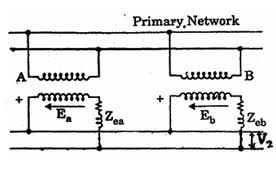
Transformers connected in parallel.
The Transformer primaries are connected in parallel across the line of distribution system and the secondaries are paralleled too. The figure above shows the parallel connection of transformers. Primary voltages across the two transformers are equal since both of them are from the same source. Ea and Eb are the induced voltages across the two transformers at no load. If the turns ratio are not equal, then Ea is not equal to Eb.
Transformer A will supply a reactive load to the secondary of Transformer B and the primary of Transformer B will feed this load back to the primary circuit. This will cause a reduction in voltage at the secondary of Transformer A and a rise in voltage on the secondary of transformer B. The Terminal voltage on the secondaries after paralleling is common to both transformers and is the voltage V2
Subscribe to RSS Feed Follow me on Twitter!